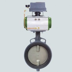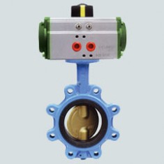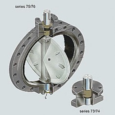
GKV710R
Technische Merkmale
Nennweiten:
DN 40– DN 600 (DN 40nur PN10/16)
Baulänge:
EN 558 Reihe 20 (DIN 3202 T3 K1)
ISO 5752 Reihe 20
API 609 Tabelle 1
BS 5155 Reihe 4
Flanschanschlussmaß:
DIN 2501 PN 6/10/16
ANSI B 16.5, Class 150
MSS SP44 Class 150
AWWA C 207
AS 2129 Tabelle D und E
BS 10 Tabelle D und E
JIS B 2211-5 K
JIS B 2212-10 K
Bördelflansche:
DIN 2641 und DIN 2642
Aufschweißflansche:
DIN 2576
Form der Gegenflanschdichtflächen:
DIN 2526, Form A-E, ANSI RF
Kopfflansch:
EN ISO 5211 NF E 29-402
Kennzeichnung:
DIN EN 19
Dichtheitsprüfung:
EN 12266 (Leckrate A)
ISO 5208, Kategorie 3
API 598 Tabelle 5
ANSI B 16-104, Class VI
Gebrauchsnorm:
EN 593 (DIN 3354)
Temperaturbereich:
–20 °C bis + 160 °C in Abhängigkeit von Druck, Medium und Werkstoff
Zul. Betriebsdruck:
max. 16 bar
Zul. Differenzdruck:
max. p 16 bar
Verwendung bei Vakuum:
bis 0,2 bar absolut, höheres Vakuum in Abhängigkeit von Medium und Temperatur

GKV720R
Technische Merkmale
Nennweiten:
DN 20 – DN 600 (DN 20 nur PN10/16)
Nennweiten:
DN 20 – DN 600 (DN 20 nur PN10/16)
Baulänge:
EN 558 Reihe 20 (DIN 3202 T3 K1)
ISO 5752 Reihe 20
API 609 Tabelle 1
BS 5155 Reihe 4
EN 558 Reihe 20 (DIN 3202 T3 K1)
ISO 5752 Reihe 20
API 609 Tabelle 1
BS 5155 Reihe 4
Flanschanschlussmaß:
DIN 2501 PN 6/10/16
ANSI B 16.5, Class 150
MSS SP44 Class 150
AWWA C 207
AS 2129 Tabelle D und E
BS 10 Tabelle D und E
JIS B 2211-5 K
JIS B 2212-10 K
DIN 2501 PN 6/10/16
ANSI B 16.5, Class 150
MSS SP44 Class 150
AWWA C 207
AS 2129 Tabelle D und E
BS 10 Tabelle D und E
JIS B 2211-5 K
JIS B 2212-10 K
Bördelflansche:
DIN 2641 und DIN 2642
DIN 2641 und DIN 2642
Aufschweißflansche:
DIN 2576
DIN 2576
Form der Gegenflanschdichtflächen:
DIN 2526, Form A-E, ANSI RF
DIN 2526, Form A-E, ANSI RF
Kopfflansch:
EN ISO 5211 NF E 29-402
EN ISO 5211 NF E 29-402
Kennzeichnung:
DIN EN 19
DIN EN 19
Dichtheitsprüfung:
EN 12266 (Leckrate A)
ISO 5208, Kategorie 3
API 598 Tabelle 5
ANSI B 16-104, Class VI
EN 12266 (Leckrate A)
ISO 5208, Kategorie 3
API 598 Tabelle 5
ANSI B 16-104, Class VI
Gebrauchsnorm:
EN 593 (DIN 3354)
EN 593 (DIN 3354)
Temperaturbereich:
–20 °C bis + 160 °C in Abhängigkeit von Druck, Medium und Werkstoff
–20 °C bis + 160 °C in Abhängigkeit von Druck, Medium und Werkstoff
Zul. Betriebsdruck:
max. 16 bar
max. 16 bar
Zul. Differenzdruck:
max. p 16 bar
max. p 16 bar
Verwendung bei Vakuum:
bis 0,2 bar absolut, höheres Vakuum in Abhängigkeit von Medium und Temperatur
bis 0,2 bar absolut, höheres Vakuum in Abhängigkeit von Medium und Temperatur

GKV730R
Technische Merkmale
Nennweiten:
DN 150 – DN 2000
Nennweiten:
DN 150 – DN 2000
Baulänge:
EN 558 Reihe 20 (DIN 3202 T3 K1)
ISO 5752 Reihe 20
API 609 Tabelle 1
NF E 29-305.1
EN 558 Reihe 20 (DIN 3202 T3 K1)
ISO 5752 Reihe 20
API 609 Tabelle 1
NF E 29-305.1
Flanschanschlussmaß:
DIN 2501 PN 6/10/16
ANSI B 16.5, Class 150
MSS SP44 Class 150
AWWA C 207
AS 2129 Tabelle D und E
BS 10 Tabelle D und E
JIS B 2211-5 K
JIS B 2212-10 K
DIN 2501 PN 6/10/16
ANSI B 16.5, Class 150
MSS SP44 Class 150
AWWA C 207
AS 2129 Tabelle D und E
BS 10 Tabelle D und E
JIS B 2211-5 K
JIS B 2212-10 K
Form der Gegenflanschdichtflächen:
DIN 2526, Form A-E, ANSI RF
DIN 2526, Form A-E, ANSI RF
Kopfflansch:
EN ISO 5211
NF E 29-402
EN ISO 5211
NF E 29-402
Kennzeichnung:
DIN EN 19
DIN EN 19
Dichtheitsprüfung:
EN 12266 (Leckrate A)
ISO 5208, Kategorie 3
API 598 Tabelle 5
ANSI B 16-104, Class VI
EN 12266 (Leckrate A)
ISO 5208, Kategorie 3
API 598 Tabelle 5
ANSI B 16-104, Class VI
Gebrauchsnorm:
EN 593 (DIN 3354)
EN 593 (DIN 3354)
Temperaturbereich:
–20 °C bis + 160 °C in Abhängigkeit von Druck, Medium und Werkstoff
–20 °C bis + 160 °C in Abhängigkeit von Druck, Medium und Werkstoff
Zul. Betriebsdruck:
max. 16 bar
max. 16 bar
Zul. Differenzdruck:
max. p 16 bar
max. p 16 bar
Verwendung bei Vakuum:
bis 0,2 bar absolut, höheres Vakuum in Abhängigkeit von Medium und Temperatur
bis 0,2 bar absolut, höheres Vakuum in Abhängigkeit von Medium und Temperatur
